

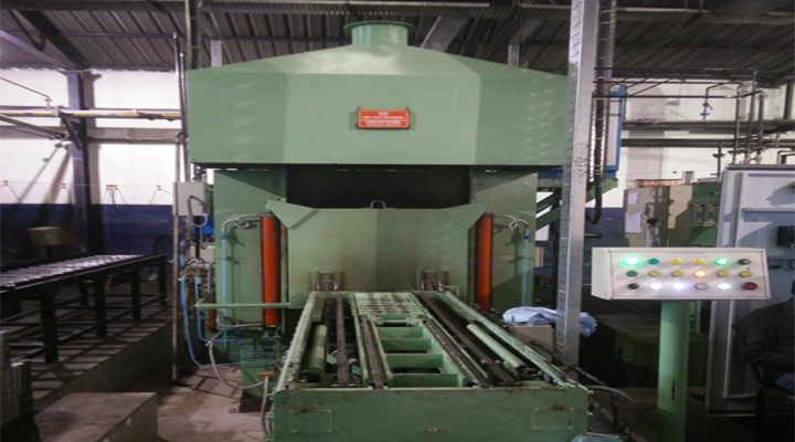


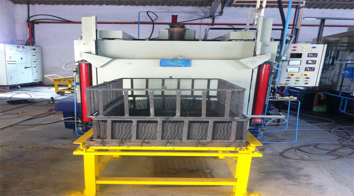
The multipurpose batch type chamber furnace plants or Sealed Quench Furnaces has revolutionized the heat treatment industry in the last few decades thanks to its versatility, easy integration in automatic treatment lines, providing flexibility of metallurgical processes, product mix and layout, with maximum quality heat treatment in terms of reliability, predictability and repetitiveness. These plants are normally coupled with companion equipment like Preheating and Tempering Furnaces, Washing Machines, Stationary Table, Scissor Lifts and fully automated one or more Charge Transfer Cars- all designed for maximum reliability.
| Sl No. | Components & Sub Assemblies. | Technical specifications: | Technical specifications: |
|---|---|---|---|
| I | TECHNICAL DATA | ||
| 1 | FURNACE type | Straight through | |
| 2 | Effective chamber Dimension | 1230 mm L x 650 mm Ht. x 750 mm W | |
| 3 | Net weight charge | 400 Kgs. | |
| 4 | Working height | 650 mm. | |
| 5 | Heat treatment process | Through hardening, gas carburising, Gas Carbonitriding, normalizing, Bright annealing. | |
| II | HEATING CHAMBER | ||
| 1 | Maximum working temp | 950℃ | |
| 2 | Temperature uniformity | ± 5℃ | |
| 3 | Heating load | 80 K.W. | |
| 4 | No. of heaters | 18 Nos. | |
| 5 | Type of heaters | Electric radiant tube. | |
| 6 | Mode of control | PID on/off. | |
| 7 | Outer radiant tube | S.S. 310 | |
| 8 | Internal construction | Bird cage element with Ni/Cr 80/20 Wire rod and sillimanite bobbins. | |
| 9 | Furnace shell | 6mm thick, gas light construction | |
| 10 | Charge support | Silicon carbide skids. | |
| 11 | Calcium silicate blocks Cold Face insulation bricks Hot face kainite insulation bricks | Hysil-Hyderabad Maithan-Chirukunda | |
| 12 | Side and rear walls | Calcium silicate blocks Cold Face insulation bricks Hot face kainite insulation blocks | Hysil-Hyderabad Maithan-Chirukunda |
| 13 | Total insulation thick | 380mm | |
| 14 | Furnace skin temperature | 60℃ above ambient | |
| 15 | FFan assembly | Shaft and impeller integral cast with Water cooled housing 2HP-1440 rpm | HU grade |
| 16 | Charge Machine | Mounted in front of heating chamber Automatic charger consisting of charging and discharging forks driven by geared motors | Kirloskar/ Bangfiliolio |
| 17 | Charge transfer from heating chamber to quenching elevator | The charging machine is lifted upto the work extracting level by an air cylinder at 5-7 kg / cm sq and the charge is discharge to the quenching tank elevator by set of discharge forks | |
| 18 | Intermediate door construction | Made from AISI-310 | |
| 19 | Intermediate door Insulation | Calcium silicate blocks Hot face kainite insulation bricks | Hysil-Hyderabad Maithan |
| 20 | Intermediate door Opening | By air cylinder at 5-7 kg/cm sq with inside movement by high temperature resistant transmission chain | Electro pneumatics |
| 21 | Intermediate door sealing | Cam locking | |
| III | VESTIBULE | ||
| 1 | Elevator | One Platform with oil quenching | |
| 2 | Loading fresh charge while previous charge under oil quenching | Possible | |
| 3 | Charge transfer b/w quench tank chamber and rear conveyor | By external motorized drive and driven rollers | |
| 4 | Status of front chamber during charge transfer b/w heating chamber to vestibule and vestibule to rear conveyor | Remains closed in sealed atmosphere | |
| 5 | Transfer of charge in sealed atmosphere during process For intermediate cooling | Possible | |
| 6 | Vestibule | Provide for faster cooling for Normalizing/ annealing. | |
| 7 | Rating of fan motor in Heating chamber | 2 HP 1440 RPM. | NGEF/Kirloskar/ Crompton Greaves. |
| 8 | Impeller diameter | 400 mm | |
| 9 | Front door seal | Completely sealed with graphitized Asbestos. | |
| 10 | Front door entry | Guide angle plate with special linkage For sealing. | |
| 11 | Furnace pressure | ± 5 -10 mm wg. | |
| 12 | Drive for elevator and rear Door | Pneumatically operated at 5 – 7 kg/cm Sq. through pneumatic cylinders. | Electro pneumatics |
| 13 | Sensing of various positions Of elevator, charge pusher And door. | Limit switches | Omron |
| 14 | Oil tank capacity | 2500 Ltrs. (Requirement). | |
| 15 | Rating of oil tank agitator Motor, | 2 Nos x 2 HP | NGEF |
| 16 | Agitator speed | Variable by variable speed drive | LG |
| 17 | Position of oil agitators | One on either side | |
| 18 | Oil agitation system | Draft tube with oil guide box | |
| 19 | Oil temperature after quenching | Up to 150℃ | |
| 20 | Quenching oil circulating Pump | Pump with mechanical seal | KSB/ Johnson |
| 21 | Heat exchanger | Water cooled-tube and shell type or air cooled. | |
| 22 | Oil level indicator | Colour coded stainless steel. | |
| 23 | Vestibule cooling | Double jacket water cooling | |
| IV. | GAS SUPPLY SYSTEM FURNACE ATMOSSPHERE | ||
| 1 | Flow meters | LPG & N₂ CH₃ OH | Instrumentation Engineers Hyderabad |
| 2 | Pressure regulators | LPG N₂CH₃OH | |
| 3 | Pressure gauges | LPG | |
| 4 | Pressure switches | LPG | |
| 5 | Non return valve | For LPG | |
| 6 | Explosion safety valve | On vestibule chamber | |
| 7 | Pilot burner & curtain Burner arrangement | 1 unit comprising of the pilot burner Curtain burner along with necessary Items like the solenoid valves, flame Failure monitor, ignition transformer, Spark plug piping valves etc. the unit Is located at the furnace entrance door, the system will ensure that Whenever either of the doors is Opened, the solenoid for the LPG is actuated and curtain burner ignites. This will help in preventing the ingress of outside atmosphere into the Chambers which hazardous | |
| 8 | Flame curtain (front & rear) | Automatic ignition by solenoid valve | Avcon |
| 9 | Furnace desooting | At end of every cycle air is introduce In the furnace hearing chamber for 5 min. for automatic desooting of Furnace , LPG is cut off during this Period. | |
| 10 | Oxygen probe carbon burnou | After the temperature attains to 920-930℃ when the charge is in the furnace heating chamber air is Purged for about 5 sec. Oxygen probe control system to Control carbon potential automatically Controlled with LPG flow control Control accuracy ±.01% | Probe make virap controller make Eurothern. |
| V | PROCESS CONTROL | ||
| 1 | 1 No. 2 set point, 2 relay output digital Output controller Range 0 - 1200℃ - K TYPE – 230 v AC For furnace temperature control. | Yokogawa/ Thoho. | |
| 2 | 1 No., single set point single relay output digital output controller Range 0-1200℃-K type-230V AC | Yokogawa/ Thoho. | |
| 3 | 2 Nos. duplex thermocouple with Cr/Al elements for furnace heating chamber | Toshniwal | |
| 4 | Electrical panel board | 1 No. of switch gear panel consisting of main isolator, power contactor and fuses, over load relays for motor circuits, control circuit transformer etc., which will be duly wired and ferruled Size: 2000mm x 2000mm x 600mm, Siemens Grey powder coated. | |
| 5 | Programmable logic control (PLC) | The PLC unit consists of the following:- Digital input module Digital output module Analog input module Digital analog out module CPU Power supply unit memory module Suitable rails and connecting cables | LG/Mitsubishi |
| 6 | Power controller | Thyristor Power Controller | IFC MAKE/Sudharshan Electronics |
| 7 | Alarm annunciation with hooter system | Alarm annunciation windows with hooter and reset button Over temperature indication Torque limiter for pusher Atmosphere circulation in the furnace heating chamber motor failure | |
| 8 | Operation Panel | A front operational is fixed on the charge pusher table housing with auto/manual selector switches. Push buttons for auto start, front door, intermediate door open/close, pusher forks forward/backward, and elevator up/down etc., which will be fully wired and tested. A rear operation panel fixed on the rear conveyor housing rear auto/manual selector switches, push buttons for elevator chain, rear conveyor forward movement, rear door open/close etc., which will be fully wired and tested. | |
| 9 | Heating transformer-50 KVA | Double wound copper warm transformer, 3 Phase AC, 50Hz, Naturally air cool | Argo Transformers Co.Pvt. Bombay/ |
| Input-400,415,440 & 460, 3 Phase AC Star connected | Output-88volt, 65 KVA, 3 Phase AC delta connected
80volt, 35KVA, 3 Phase delta Connected |
TS International | |
| 10 | Touch Screen | Touch screen is provided for the operator to set the parameters like time, temperature (main furnace temperature and oil tank temperature) and process cycle for the process in the furnace | Pro-face-digital Model-GP-37W2B Screen size-5.7'' Display type-Monochrome blue-mode LCD Display Colours-Blue and White Digital-Japan |
| IV | PAINTING | An attractive colour paint of your choice. |
| Shell | : This will be a M.S. plate welded fabrication with reinforcement. The surface will be provided with rust preventive coating and will be finished with neatly and attractive colour of your choice. Base support stand designed for the working height is provided. |
| Front door | M.S. Plate fabricated and duly reinforced door is provided, door is brick lined. The operation of the door is pneumatic for which the necessary cylinder, FLR, solenoids, flow regulators, silencers, valves, piping etc. are provided. Suitable sealing and guide arrangements are provided for the door to prevent heat leakage. |
| Insulation | : 1st layer each of hot face 115 mm & 115 mm cold face insulation bricks and 50 mm Hysil board are provided on all the sides to a total thickness of 380 mm. |
| Intermediate door | M.S.Plate fabricated and duly reinforced door is provided Door is brick lined. The operation of the door is for which the necessary cylinders, FLR, solenoids, flow pneumatic regulators, silencers, valve, piping etc., are provided. Suitable sealing and guide arrangements are provided for the door to prevent heat leakage. |
| Circulation arrangements | : This will comprise of a driven by a motor mounted on the top the fan assembly will dynamically balance. The drive for the fan will be direct and the necessary stand, coupling, Bearing, cooling block etc. are provided. The fan and the Speed of the motor will be designed to give a minimum displacements to ensure uniformity at lower operating temperature. |
| Pilot burner & curtain burner Arrangement | One unit comprising of the pilot burner, curtain burner along with the necessary items like the solenoid valve, flame failure monitor, ignition transformer, spark plug, piping, valves etc., the unit is located at the furnace entrance door. The system will ensure that whenever the door is opened, the solenoid for the LPG is actuated and the curtain burner ignites. This will help in preventing the entry of outside atmosphere into the chambers, which is hazardous. |
| Flow meter panel | The flow meter panel will be a MS fabrication comprising of M.S. Plate supported on a M.S. frame of angles and channels. All the flow meters will be mounted on the front of the M.S. plate. The flow meter panel will be given rust preventive
coating and will be finished with RAL Green colour. All necessary items like the pressure
reducers, pressure gauges, solenoid valves, ball valves, piping and fitting will be provided, as required for the respective flow meters. The inter connecting piping and fittings between the flow meter panel and the equipment is not considered in our scope. |
| Temperature indication & control | To indicate and control the furnace temperature, a digital controller is provided. As a safety backup, for excess temperature control, a non-indicating controller is provided. These controllers will act in conjunction with the thermocouples provided to sense the furnace temperature. |
| Electrical switch gear | The necessary items like the main switch, heaters & motor contactor, fuses, lamps, switches., MCB, OLR, limit switches, etc., are provided for the heater, motor and control circuits. Each switch gear items is carefully designed and selected and selected to suit the application. |
| Control Panel | This will be a self-standing, MS cubicle with hinged, front access door. The control panel will be powder coated with Siemens gray paint and the mounting plate will be orange powder coated. The control panel will be fully wired and tested before dispatch. |